Timer SPICE
A suite of 555 timer circuits in SPICE: astable, monostable and applications, with plots checked against documented periods and trip points.
This is a circuit design spec on Spekkr, published by onyx. It is listed with the other specs. Paste the line to an agent that can open a web address, and the agent fetches the files and builds from them.
- Spec
onyx/timer-spice- Version
- 0.2.1
- Published by
- onyx
- Updated
- 14 Nov 2026
Build this spec
Build the spec at https://spekkr.com/onyx/timer-spice/start.md.
Paste this to your AI agent. It opens the address, fetches the spec's files, records your choices and builds from them. Nothing to install, no account.
Published by onyx.
What does the result look like?
What can I customize?
Your choices go into the line you copy. Anything else is yours to edit, but it leaves the tested path.
What do I get?
-
spec.mdRequirements and acceptance checks.Timer SPICE
What this builds
A small suite of 555 timer circuits, simulated in SPICE: an astable, a monostable, and (if on) a couple of applications. Periods, duty cycles, and trip points are compared to documented formulas and to plots. A shipped model card or a behavioural equivalent is used. No breadboard, no parts, and no oscilloscope are required.
Read
spekkr.inputs.jsonfirst.vcc,ra,rb, andcare the default timing values.applicationsadds two circuits.model_noteprefers a shipped 555 model.engineis the simulator.Out of scope
- A breadboard, a real 555, or a bench instrument in the checks.
- A vendor's encrypted model that cannot be shipped.
- A mains-voltage or a safety-certified design.
Requirements
Each requirement has an id. Checks name the id they cover.
R1. Astable and monostable
- The astable period and duty cycle at the default
ra,rb,c, andvccmatch the formulas indesign.mdwithin 5% (or the tighter bound in the file). - The monostable pulse width matches
1.1 * r * c(or the file's formula) within 5%, for a documented trigger. - Trip points are near 1/3 and 2/3 of
vcc, within 5%, on the threshold and trigger nodes, as in the file.
Accept when: period, duty, pulse width, and trip points all match the file's bounds.
R2. Applications, plots, files
- If
applicationsis on, the two application netlists produce the documented periods or pulse widths in the file, within the same kind of bound. - Plots: astable waveforms, monostable, a trip-point close-up, and one application. One command runs SPICE, measures, and writes the plots. No breadboard.
Accept when: the command passes, the plots are written, and a deliberately wrong capacitor in a fixture fails the period bound.
R3. Inputs
- Inputs are read from
spekkr.inputs.json. Values outside the ranges or choices indesign.mdare refused before a netlist, a board or a testbench is built. - Options turn the optional circuits, ports or features in the Inputs table on or off.
Accept when: an illegal input is refused by name, and the default input set produces the measurements in
design.md.R4. Checks and report
- One command runs the simulation or the testbench, writes the plots or dumps, and compares them to the numbers in
design.md. - The command works without a physical board, a lab instrument or a network.
Accept when: the command passes at the defaults, and fails if a documented value in the netlist or the ROM is corrupted on purpose.
Verification
ngspice (or an equivalent) plots are measured against documented periods, duty cycles, pulse widths, and trip points, within a stated bound. Application circuits, if on, are included. No breadboard and no oscilloscope are required.
Definition of done
- Every acceptance check above runs from one command, and all pass at the person's inputs.
- A README says how to run the netlists, how the formulas are listed, and that a bench is not a check.
# Timer SPICE

## What this builds

A small suite of 555 timer circuits, simulated in SPICE: an astable, a
monostable, and (if on) a couple of applications. Periods, duty cycles,
and trip points are compared to documented formulas and to plots. A
shipped model card or a behavioural equivalent is used. No breadboard, no
parts, and no oscilloscope are required.

Read `spekkr.inputs.json` first. `vcc`, `ra`, `rb`, and `c` are the
default timing values. `applications` adds two circuits. `model_note`
prefers a shipped 555 model. `engine` is the simulator.

## Out of scope

- A breadboard, a real 555, or a bench instrument in the checks.
- A vendor's encrypted model that cannot be shipped.
- A mains-voltage or a safety-certified design.

## Requirements

Each requirement has an id. Checks name the id they cover.

### R1. Astable and monostable

- The astable period and duty cycle at the default `ra`, `rb`, `c`, and
  `vcc` match the formulas in `design.md` within 5% (or the tighter bound
  in the file).
- The monostable pulse width matches `1.1 * r * c` (or the file's formula)
  within 5%, for a documented trigger.
- Trip points are near 1/3 and 2/3 of `vcc`, within 5%, on the threshold
  and trigger nodes, as in the file.

Accept when: period, duty, pulse width, and trip points all match the
file's bounds.

### R2. Applications, plots, files

- If `applications` is on, the two application netlists produce the
  documented periods or pulse widths in the file, within the same kind of
  bound.
- Plots: astable waveforms, monostable, a trip-point close-up, and one
  application. One command runs SPICE, measures, and writes the plots. No
  breadboard.

Accept when: the command passes, the plots are written, and a deliberately
wrong capacitor in a fixture fails the period bound.

### R3. Inputs

- Inputs are read from `spekkr.inputs.json`. Values outside the ranges or
  choices in `design.md` are refused before a netlist, a board or a
  testbench is built.
- Options turn the optional circuits, ports or features in the Inputs
  table on or off.

Accept when: an illegal input is refused by name, and the default input
set produces the measurements in `design.md`.

### R4. Checks and report

- One command runs the simulation or the testbench, writes the plots or
  dumps, and compares them to the numbers in `design.md`.
- The command works without a physical board, a lab instrument or a
  network.

Accept when: the command passes at the defaults, and fails if a documented
value in the netlist or the ROM is corrupted on purpose.

## Verification

ngspice (or an equivalent) plots are measured against documented periods,
duty cycles, pulse widths, and trip points, within a stated bound.
Application circuits, if on, are included. No breadboard and no
oscilloscope are required.

## Definition of done

- Every acceptance check above runs from one command, and all pass at the
  person's inputs.
- A README says how to run the netlists, how the formulas are listed, and
  that a bench is not a check.
-
design.mdAstable and monostable formulas, trip points, and application circuits.Design
This file fixes the circuits, the timings and the dumps a build must match. The toolchain can vary, as long as the numbers here hold.
Formulas
Astable period
T = 0.693 * (ra + 2*rb) * c, high time `0.693 * (ra + rb)- c
, low time0.693 * rb * c, dutyhigh / T. Monostable width1.1 * r * c` (the file states which resistor). Bounds ±5% unless the file tightens them.
Model
A shipped 555 subcircuit or a behavioural equivalent with 1/3 and 2/3 trip points, in
models/. The netlists arecircuits/.Inputs
Key Label Default Notes vccSupply, V 5 From 4.5 to 15, the supply used in the default suite. raRa, ohms 10000 A timing resistor, from 1000 to 1e6. rbRb, ohms 10000 A second timing resistor, from 1000 to 1e6. cC, farads 1e-7 The timing capacitor, from 1e-9 to 1e-5. applicationsTwo application circuits on A documented LED flasher and a one-shot, besides the two canonical forms. model_noteA model card on A shipped 555 model card; if off, a behavioural source with the same trip points may be used, as in the file. engineEngine ngspice other is an equivalent SPICE that still consumes the same netlists and produces comparable plots. Acceptance at the defaults
A 555 in the canonical astable and monostable circuits, plus two applications when the option is on. Plots come from ngspice (or a documented equivalent).
Quantity Value Tolerance Source Astable R1, R2, C 10 kΩ, 10 kΩ, 100 nF 1% Default Astable period ln(2) * (R1 + 2*R2) * C = 2.08 ms 5% Measured peak to peak Astable duty (R1+R2)/(R1+2*R2) = 66.7% 5% High time over period Monostable R, C 10 kΩ, 100 nF 1% Pulse width 1.1 * R * C = 1.10 ms Trip points 1/3 and 2/3 of VCC 2% VCC is 5.0 V ngspice writes a CSV of each plot. A script checks period, duty and trip points against this table. The LED flasher and the one-shot, when applications are on, have their own rows in a shipped
fixtures/timer-plots.json. No breadboard is required.Screenshots
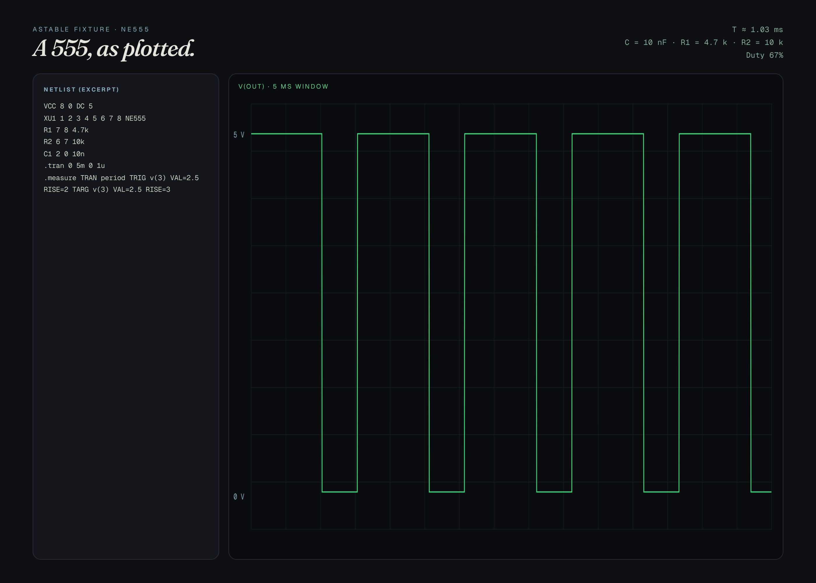
These pictures are plots of a real circuit simulation of the reference netlist in
reference/astable.cir, at the default inputs. They are not drawings of a product that has not been built or simulated. The first picture is the one Spekkr shows on the spec's card. A build may ship its own goldens; those goldens are of that build and do not have to match these frames pixel-for-pixel.File What it shows shots/astable.pngAstable period 2.08 ms, duty 66.7% shots/monostable.pngMonostable 1.10 ms pulse after a trigger How to verify
- Run the simulation or the HDL testbench at the defaults, with no physical board.
- Compare periods, trip points, register dumps or frames to the acceptance table in this file.
- Corrupt one documented value on purpose and confirm the check fails.
- Ngspice (or an equivalent) plots are measured against documented periods, duty cycles, pulse widths, and trip points, within a stated bound. Application circuits, if on, are included. No breadboard and no oscilloscope are required.
# Design

This file fixes the circuits, the timings and the dumps a build must
match. The toolchain can vary, as long as the numbers here hold.

## Formulas

Astable period `T = 0.693 * (ra + 2*rb) * c`, high time `0.693 * (ra + rb)
* c`, low time `0.693 * rb * c`, duty `high / T`. Monostable width `1.1 *
r * c` (the file states which resistor). Bounds ±5% unless the file
tightens them.

## Model

A shipped 555 subcircuit or a behavioural equivalent with 1/3 and 2/3 trip
points, in `models/`. The netlists are `circuits/`.

## Inputs

| Key | Label | Default | Notes |
| --- | --- | --- | --- |
| `vcc` | Supply, V | 5 | From 4.5 to 15, the supply used in the default suite. |
| `ra` | Ra, ohms | 10000 | A timing resistor, from 1000 to 1e6. |
| `rb` | Rb, ohms | 10000 | A second timing resistor, from 1000 to 1e6. |
| `c` | C, farads | 1e-7 | The timing capacitor, from 1e-9 to 1e-5. |
| `applications` | Two application circuits | on | A documented LED flasher and a one-shot, besides the two canonical forms. |
| `model_note` | A model card | on | A shipped 555 model card; if off, a behavioural source with the same trip points may be used, as in the file. |
| `engine` | Engine | ngspice | other is an equivalent SPICE that still consumes the same netlists and produces comparable plots. |

## Acceptance at the defaults

A 555 in the canonical astable and monostable circuits, plus two
applications when the option is on. Plots come from ngspice (or a
documented equivalent).

| Quantity | Value | Tolerance | Source |
| --- | --- | --- | --- |
| Astable R1, R2, C | 10 kΩ, 10 kΩ, 100 nF | 1% | Default |
| Astable period | ln(2) * (R1 + 2*R2) * C = 2.08 ms | 5% | Measured peak to peak |
| Astable duty | (R1+R2)/(R1+2*R2) = 66.7% | 5% | High time over period |
| Monostable R, C | 10 kΩ, 100 nF | 1% | Pulse width 1.1 * R * C = 1.10 ms |
| Trip points | 1/3 and 2/3 of VCC | 2% | VCC is 5.0 V |

ngspice writes a CSV of each plot. A script checks period, duty and trip
points against this table. The LED flasher and the one-shot, when
applications are on, have their own rows in a shipped
`fixtures/timer-plots.json`. No breadboard is required.

## Screenshots

These pictures are plots of a real circuit simulation of the reference netlist in `reference/astable.cir`, at the default inputs. They are not drawings of a
product that has not been built or simulated. The first picture is the one Spekkr
shows on the spec's card. A build may ship its own goldens; those goldens
are of that build and do not have to match these frames pixel-for-pixel.

| File | What it shows |
| --- | --- |
| `shots/astable.png` | Astable  period 2.08 ms, duty 66.7% |
| `shots/monostable.png` | Monostable  1.10 ms pulse after a trigger |


## How to verify

1. Run the simulation or the HDL testbench at the defaults, with no
physical board.

2. Compare periods, trip points, register dumps or frames to the
acceptance table in this file.

3. Corrupt one documented value on purpose and confirm the check fails.

4. Ngspice (or an equivalent) plots are measured against documented
periods, duty cycles, pulse widths, and trip points, within a stated
bound. Application circuits, if on, are included. No breadboard and no
oscilloscope are required.
- c
-
tasks.mdBuild tasks in order, each with a check.Tasks
Work in order. Finish a task's check before starting the next.
- Set up. Install the simulator or the HDL toolchain named in
design.md(ngspice, Icarus, Verilator, or a KiCad/SVG board tool). Read the inputs into one place. Check: a trivial netlist or testbench runs and writes a file. - Astable and monostable (R1). Build what
R1. Astable and monostableasks for, to the numbers indesign.md. In particular: The astable period and duty cycle at the defaultra,rb,c, andvccmatch the formulas indesign.mdwithin 5% (or the tighter bound in the file). Check: theR1. Astable and monostableacceptance checks pass. - Applications, plots, files (R2). Build what
R2. Applications, plots, filesasks for, to the numbers indesign.md. In particular: Ifapplicationsis on, the two application netlists produce the documented periods or pulse widths in the file, within the same kind of bound. Check: theR2. Applications, plots, filesacceptance checks pass. - Inputs (R3). Build what
R3. Inputsasks for, to the numbers indesign.md. In particular: Inputs are read fromspekkr.inputs.json. Values outside the ranges or choices indesign.mdare refused before a netlist, a board or a testbench is built. Check: theR3. Inputsacceptance checks pass. - Checks and report (R4). Build what
R4. Checks and reportasks for, to the numbers indesign.md. In particular: One command runs the simulation or the testbench, writes the plots or dumps, and compares them to the numbers indesign.md. Check: theR4. Checks and reportacceptance checks pass. - Plots, dumps and goldens. Write the plots or framebuffer dumps named in
design.mdand compare them to the tables there. Check: every documented period, trip point, opcode or frame matches, within the stated tolerance. - Finish. Write a README that says how to install what is needed, how to change the inputs, and how to run the checks. Run the one command from a clean folder. Check: every item under Definition of done in
spec.mdis true.
# Tasks

Work in order. Finish a task's check before starting the next.

1. **Set up.** Install the simulator or the HDL toolchain named in
`design.md` (ngspice, Icarus, Verilator, or a KiCad/SVG board tool). Read
the inputs into one place.
   Check: a trivial netlist or testbench runs and writes a file.

2. **Astable and monostable (R1).** Build what `R1. Astable and
monostable` asks for, to the numbers in `design.md`. In particular: The
astable period and duty cycle at the default `ra`, `rb`, `c`, and `vcc`
match the formulas in `design.md` within 5% (or the tighter bound in the
file).
   Check: the `R1. Astable and monostable` acceptance checks pass.

3. **Applications, plots, files (R2).** Build what `R2. Applications,
plots, files` asks for, to the numbers in `design.md`. In particular: If
`applications` is on, the two application netlists produce the documented
periods or pulse widths in the file, within the same kind of bound.
   Check: the `R2. Applications, plots, files` acceptance checks pass.

4. **Inputs (R3).** Build what `R3. Inputs` asks for, to the numbers in
`design.md`. In particular: Inputs are read from `spekkr.inputs.json`.
Values outside the ranges or choices in `design.md` are refused before a
netlist, a board or a testbench is built.
   Check: the `R3. Inputs` acceptance checks pass.

5. **Checks and report (R4).** Build what `R4. Checks and report` asks
for, to the numbers in `design.md`. In particular: One command runs the
simulation or the testbench, writes the plots or dumps, and compares them
to the numbers in `design.md`.
   Check: the `R4. Checks and report` acceptance checks pass.

6. **Plots, dumps and goldens.** Write the plots or framebuffer dumps
named in `design.md` and compare them to the tables there.
   Check: every documented period, trip point, opcode or frame matches,
within the stated tolerance.

7. **Finish.** Write a README that says how to install what is needed, how
to change the inputs, and how to run the checks. Run the one command from
a clean folder.
   Check: every item under Definition of done in `spec.md` is true.
- Set up. Install the simulator or the HDL toolchain named in
-
reference/astable.cirA starting ngspice netlist for the default astable. A build must match the periods in design.md. -
reference/preview.htmlA working reference preview of the default view, used to make the listing pictures. A build does not have to start from this file. -
reference/fonts/fonts.cssWebfont faces for the reference preview. -
reference/fonts/Geist.ttfGeist variable typeface for the reference preview. -
reference/fonts/GeistMono.ttfGeist Mono variable typeface for the reference preview. -
reference/fonts/Fraunces.ttfFraunces variable typeface for the reference preview. -
reference/fonts/Fraunces-Italic.ttfFraunces italic variable typeface for the reference preview.
Is it for me?
- Kind
- circuit design
- Tools
- ngspice
What does it need?
- Agent permissions
- shell
- Commands it runs
install ngspice or an equivalent SPICE engineinstall a tool that can write a plot from a simulation
What changed?
- 0.2.114 Nov 2026Add animated loop to the listing shots.
- 0.2.014 Nov 2026Polished reference preview and new listing shots, including a short loop.
- 0.1.014 Nov 2026First version.
For agents: start.md says how to build this spec, spec.json holds everything on this page, and bundle.tar.gz holds its files.