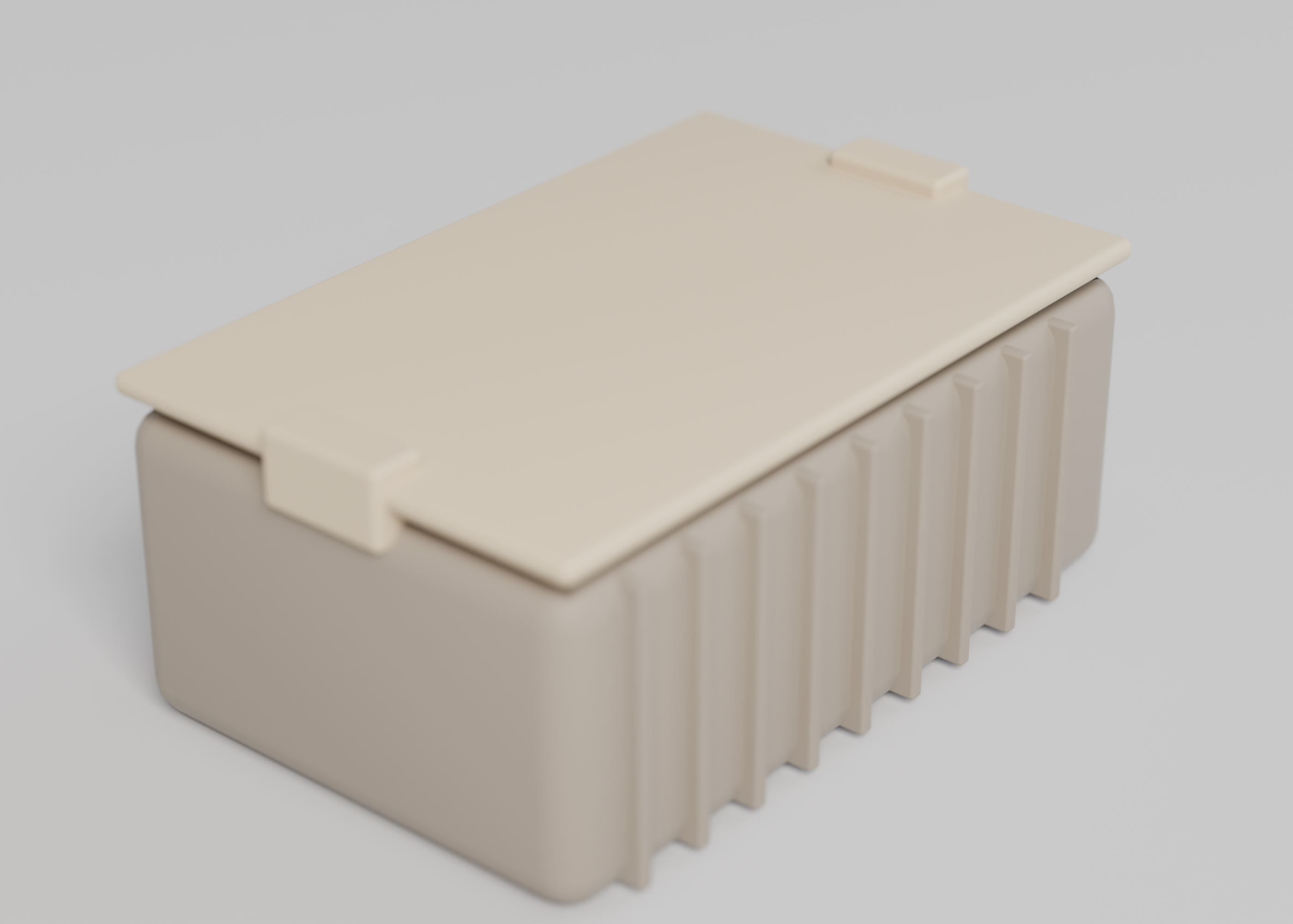
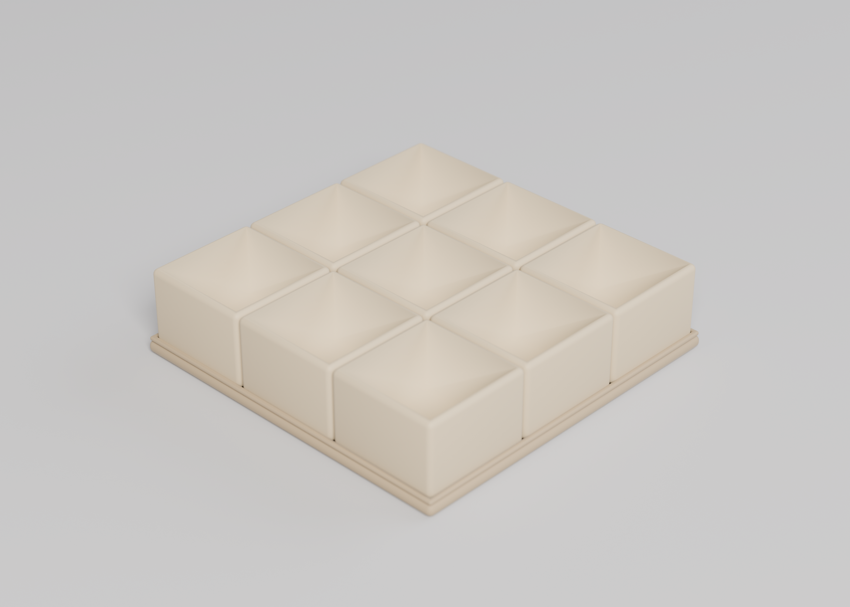
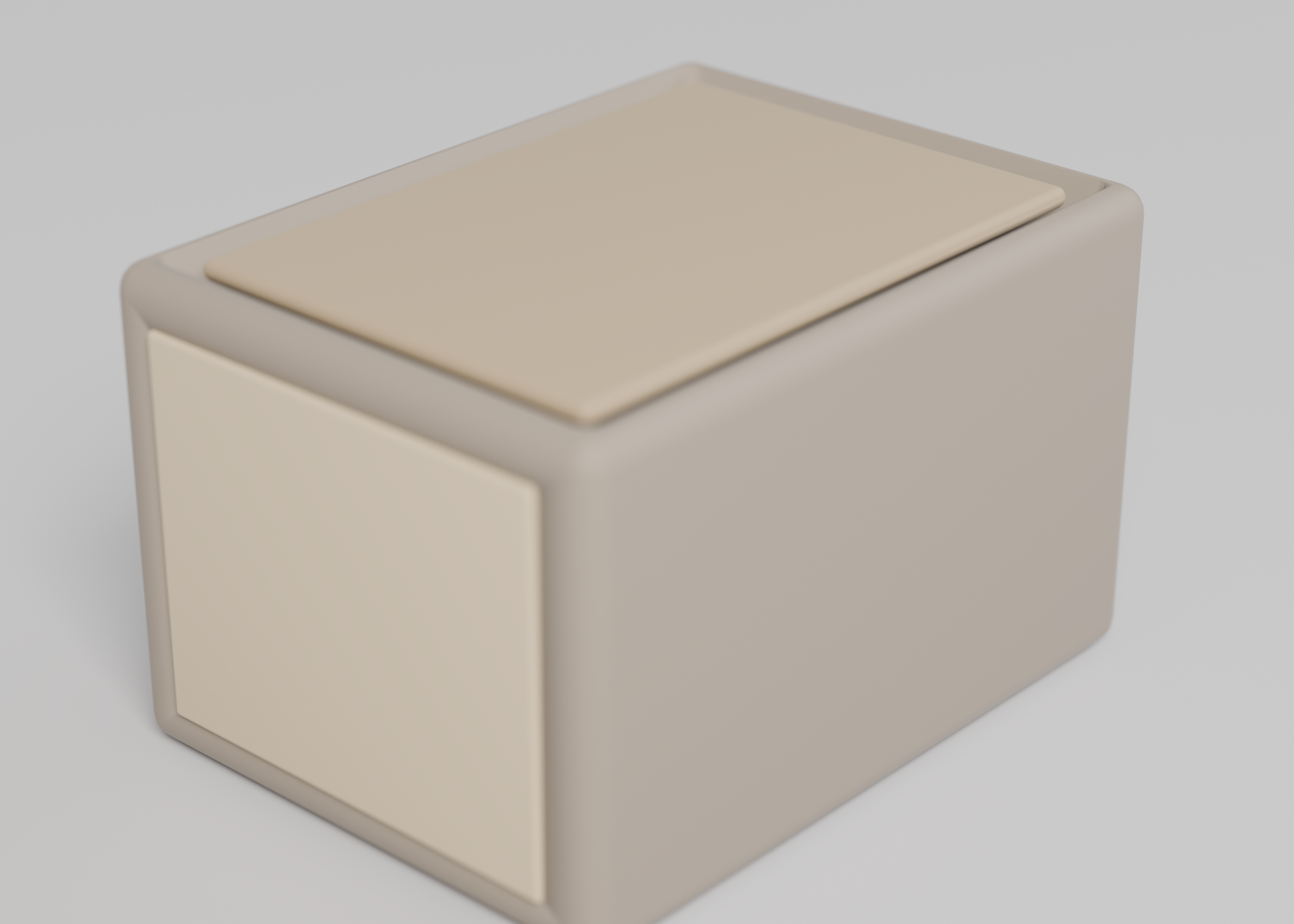
Enclosure for a circuit board
A two-part printable enclosure sized to your board, modelled as code, with dimensions and volumes a build must reproduce.
This is a CAD spec on Spekkr, published by onyx. It is listed with the other specs. Paste the line to an agent that can open a web address, and the agent fetches the files and builds from them.
- Spec
onyx/project-enclosure- Version
- 0.1.1
- Published by
- onyx
- Updated
- 14 Nov 2026
Build this spec
Build the spec at https://spekkr.com/onyx/project-enclosure/start.md.
Paste this to your AI agent. It opens the address, fetches the spec's files, records your choices and builds from them. Nothing to install, no account.
Published by onyx.
What does the result look like?
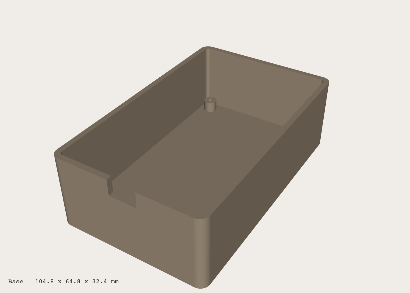
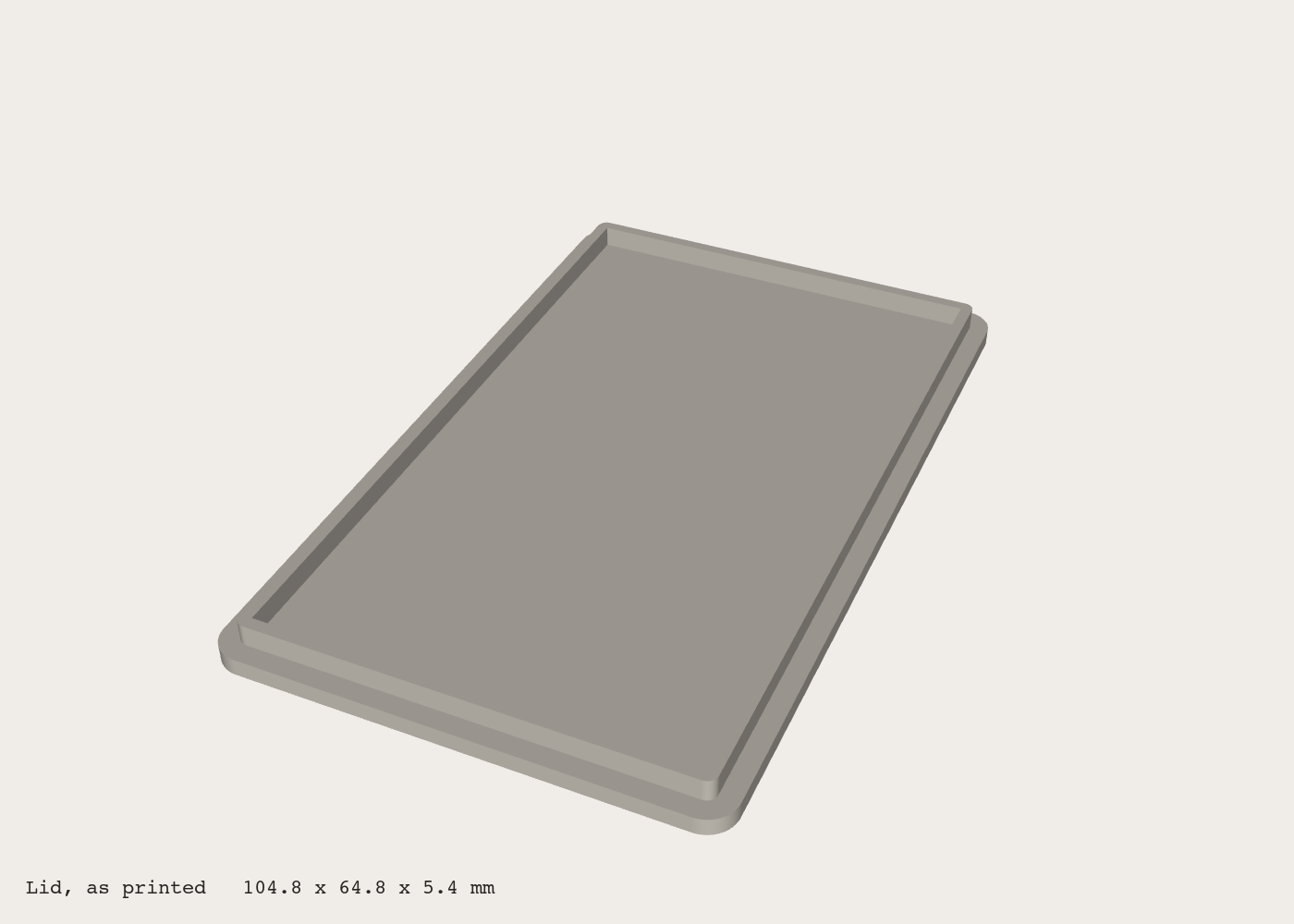
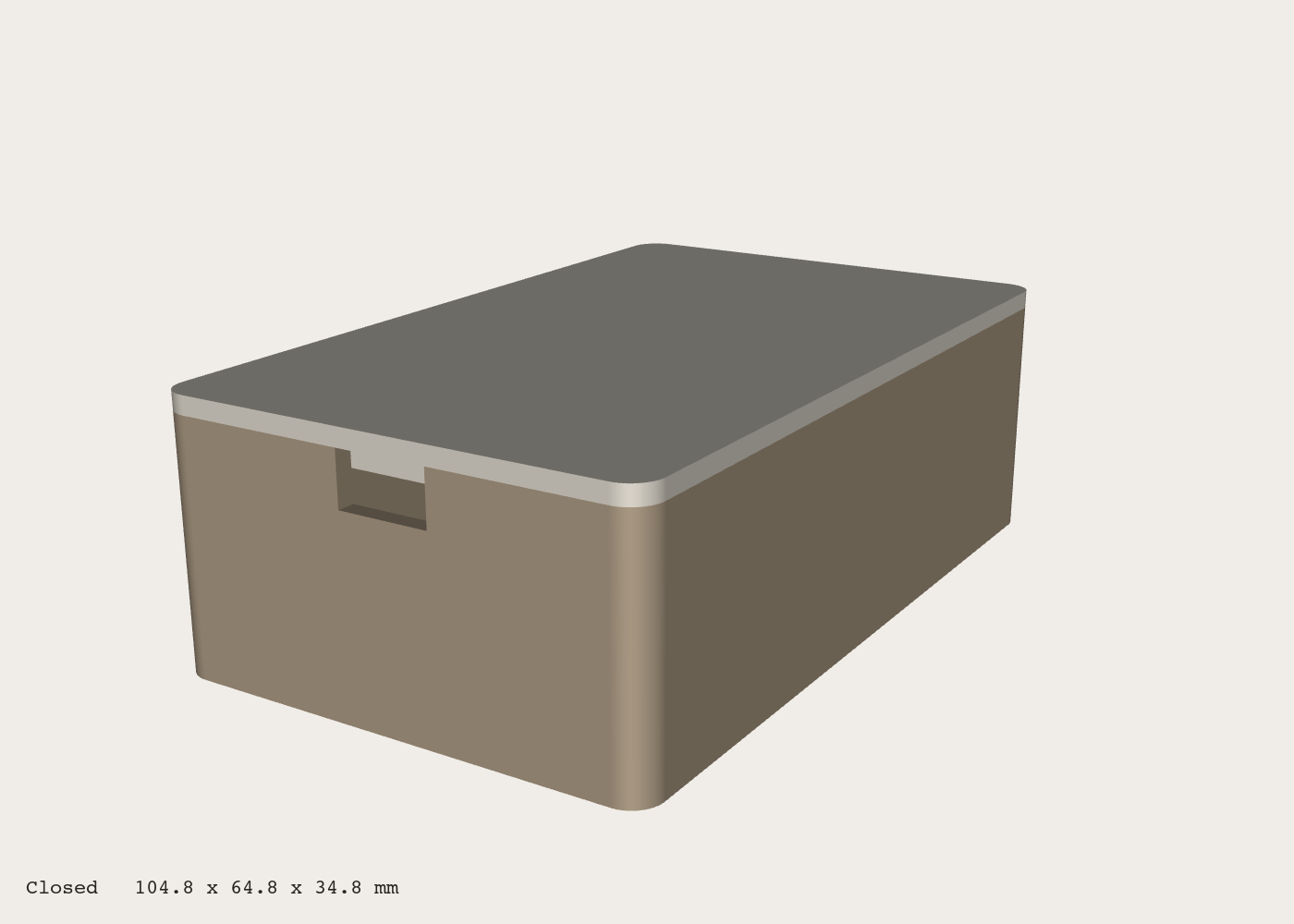
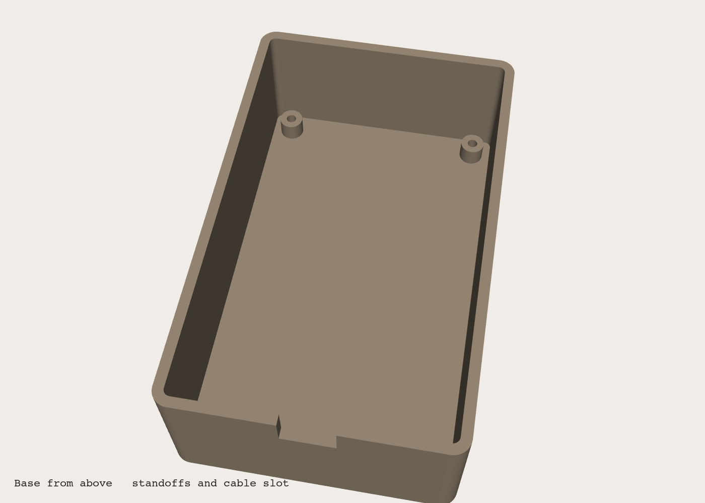
What can I customize?
Your choices go into the line you copy. Anything else is yours to edit, but it leaves the tested path.
What do I get?
-
spec.mdRequirements and acceptance checks.Enclosure for a circuit board
What this builds
A box and a lid for a circuit board, to print on a 3D printer. The model is written as code, so the size follows the person's numbers, and a script measures what was built against what this spec says it must be.
Read
spekkr.inputs.jsonfirst. The inside of the box isinner_lengthbyinner_widthbyinner_height, the walls arewallthick, and the outside corners havecorner_radius.standoffsandcable_slotadd features.toolsays what the model is written in. All lengths are millimetres.Out of scope
- Screws through the lid, hinges and seals. The lid is held by its fit.
- Openings for particular connectors, displays or buttons.
- Slicing for a particular printer.
Requirements
Each requirement has an id. Checks name the id they cover.
R1. Inputs
- The five lengths are numbers.
wallis from 1.2 to 5.corner_radiusis 0 or more, and at most half the smaller outside side. - The inside must be at least 20 by 20 by 10.
- A value outside these is refused before anything is modelled, with a message that names the input and the limit.
Accept when: each limit has a check with a value just inside and one just outside.
R2. The base
- An open box. Its outside is
inner_lengthplus two walls long,inner_widthplus two walls wide, andinner_heightplus one wall high. The floor is one wall thick. - The four vertical outside edges are rounded with
corner_radius. The inside corners are rounded with that radius less one wall, or square if that is not more than zero. No other edge is rounded. - The origin is the centre of the outside of the floor, with the box rising along +Z.
Accept when: the base's bounding box and volume match
design.mdat the default inputs, and match the formulas there at two other sets of inputs.R3. Standoffs
Only if
standoffsis on.- Four posts rise 5 from the floor, each 6 across with a pilot hole 2.5 across down its full height, for an M3 self-tapping screw. The hole does not go into the floor.
- Their centres are 5 in from each inside wall.
Accept when: the base's volume grows by the amount in
design.md, and the four centres are where the table there puts them.R4. Cable slot
Only if
cable_slotis on.- A slot 12 wide and 7 deep, cut down from the top edge of the short wall at +X, centred across that wall, through the whole wall.
Accept when: the base's volume shrinks by the amount in
design.md.R5. The lid
- A plate with the same outline as the base, one wall thick.
- Under it, a lip 3 high and 1.6 thick that goes inside the base. There is 0.2 between the lip and the inside of the walls, all the way round.
- Modelled in the position it prints in: plate down, lip up.
Accept when: the lid's bounding box and volume match
design.md, and with the lid placed on the base the two solids do not overlap anywhere.R6. Printable
- Each part prints flat side down with no support: nothing overhangs by more than 45 degrees from vertical.
- Each part is one closed solid, with no holes in its surface and no faces that pass through each other.
Accept when: a mesh check reports each exported part as watertight, and a check of face directions finds no overhang past 45 degrees in the print position.
R7. Files
baseandlidas separate files: STEP and STL iftooliscadquery, STL if it isopenscad.- STL files are in millimetres, with curves fine enough that no flat piece of a rounded corner is longer than 0.5.
- The source that makes them, and one command that makes everything from the inputs.
Accept when: running the command from a clean folder writes every file, and running it twice writes the same bytes.
R8. A report
- The command ends by writing
report.md: the inputs, each part's bounding box and volume, whatdesign.mdsays they should be, and pass or fail for each.
Accept when: the report is written, and a deliberately wrong wall thickness in the model makes it say fail.
Definition of done
- Every acceptance check above runs from one command, and all pass at the person's inputs.
- A README says how to install the tool, how to make the parts, how to print them, and what the lid's fit was designed for.
# Enclosure for a circuit board

## What this builds

A box and a lid for a circuit board, to print on a 3D printer. The model is
written as code, so the size follows the person's numbers, and a script measures
what was built against what this spec says it must be.

Read `spekkr.inputs.json` first. The inside of the box is `inner_length` by
`inner_width` by `inner_height`, the walls are `wall` thick, and the outside
corners have `corner_radius`. `standoffs` and `cable_slot` add features. `tool`
says what the model is written in. All lengths are millimetres.

## Out of scope

- Screws through the lid, hinges and seals. The lid is held by its fit.
- Openings for particular connectors, displays or buttons.
- Slicing for a particular printer.

## Requirements

Each requirement has an id. Checks name the id they cover.

### R1. Inputs

- The five lengths are numbers. `wall` is from 1.2 to 5. `corner_radius` is 0 or
  more, and at most half the smaller outside side.
- The inside must be at least 20 by 20 by 10.
- A value outside these is refused before anything is modelled, with a message
  that names the input and the limit.

Accept when: each limit has a check with a value just inside and one just outside.

### R2. The base

- An open box. Its outside is `inner_length` plus two walls long, `inner_width`
  plus two walls wide, and `inner_height` plus one wall high. The floor is one
  wall thick.
- The four vertical outside edges are rounded with `corner_radius`. The inside
  corners are rounded with that radius less one wall, or square if that is not
  more than zero. No other edge is rounded.
- The origin is the centre of the outside of the floor, with the box rising
  along +Z.

Accept when: the base's bounding box and volume match `design.md` at the default
inputs, and match the formulas there at two other sets of inputs.

### R3. Standoffs

Only if `standoffs` is on.

- Four posts rise 5 from the floor, each 6 across with a pilot hole 2.5 across
  down its full height, for an M3 self-tapping screw. The hole does not go into
  the floor.
- Their centres are 5 in from each inside wall.

Accept when: the base's volume grows by the amount in `design.md`, and the four
centres are where the table there puts them.

### R4. Cable slot

Only if `cable_slot` is on.

- A slot 12 wide and 7 deep, cut down from the top edge of the short wall at +X,
  centred across that wall, through the whole wall.

Accept when: the base's volume shrinks by the amount in `design.md`.

### R5. The lid

- A plate with the same outline as the base, one wall thick.
- Under it, a lip 3 high and 1.6 thick that goes inside the base. There is 0.2
  between the lip and the inside of the walls, all the way round.
- Modelled in the position it prints in: plate down, lip up.

Accept when: the lid's bounding box and volume match `design.md`, and with the lid
placed on the base the two solids do not overlap anywhere.

### R6. Printable

- Each part prints flat side down with no support: nothing overhangs by more than
  45 degrees from vertical.
- Each part is one closed solid, with no holes in its surface and no faces that
  pass through each other.

Accept when: a mesh check reports each exported part as watertight, and a check
of face directions finds no overhang past 45 degrees in the print position.

### R7. Files

- `base` and `lid` as separate files: STEP and STL if `tool` is `cadquery`, STL if
  it is `openscad`.
- STL files are in millimetres, with curves fine enough that no flat piece of a
  rounded corner is longer than 0.5.
- The source that makes them, and one command that makes everything from the
  inputs.

Accept when: running the command from a clean folder writes every file, and
running it twice writes the same bytes.

### R8. A report

- The command ends by writing `report.md`: the inputs, each part's bounding box
  and volume, what `design.md` says they should be, and pass or fail for each.

Accept when: the report is written, and a deliberately wrong wall thickness in the
model makes it say fail.

## Definition of done

- Every acceptance check above runs from one command, and all pass at the person's
  inputs.
- A README says how to install the tool, how to make the parts, how to print
  them, and what the lid's fit was designed for.
-
design.mdGeometry, formulas and the numbers a build must match.Design
This file fixes the geometry. How the model's code is organised is up to you.
Sizes
All in millimetres. Write
L,W,Hfor the inside length, width and height,tforwallandrforcorner_radius.Length (X) Width (Y) Height (Z) Base L + 2tW + 2tH + tLid, as printed L + 2tW + 2tt + 3Closed L + 2tW + 2tH + 2tAt the defaults: the base is 104.8 by 64.8 by 32.4, the lid 104.8 by 64.8 by 5.4, and the closed box 34.8 high.
Volumes
The area of a rectangle
abybwith corners of radiusc:area(a, b, c) = a * b - (4 - pi) * c * cshell = area(L + 2t, W + 2t, r) * (H + t) - area(L, W, max(r - t, 0)) * H standoffs = 4 * (pi / 4) * (6 * 6 - 2.5 * 2.5) * 5 slot = 12 * 7 * t base = shell + standoffs (if on) - slot (if on) plate = area(L + 2t, W + 2t, r) * t lip = ( area(L - 0.4, W - 0.4, max(r - t - 0.2, 0)) - area(L - 3.6, W - 3.6, 0) ) * 3 lid = plate + lipAt the defaults, in cubic millimetres, to the nearest one:
Part Volume Base, no standoffs, no cable slot 39,651 Base, with 4 standoffs 40,118 Base, with 4 standoffs and the cable slot 39,916 Lid 17,758 A measured volume passes when it is within 0.5% of the formula. A bounding box passes when each side is within 0.05.
Where things are
Feature Position Standoff centres X = +/-(L/2 - 5),Y = +/-(W/2 - 5); at the defaults(+/-45, +/-25)Standoffs From Z = ttoZ = t + 5Cable slot In the wall at X = +L/2, fromY = -6toY = +6, fromZ = H + t - 7upLip, lid as printed From Z = ttoZ = t + 3How to model it
- Draw each outline in 2D as a rounded rectangle and extrude it. Rounding edges of a 3D box afterwards rounds edges this spec leaves sharp.
- Keep every number in one place at the top of the source, read from the inputs.
- With
toolset toopenscad, set$fnfrom the largest radius in the part,r, so that R7's rule on flat pieces holds. A circle drawn withnflat pieces has pieces2 * r * sin(180 / n)long, so use the smallest multiple of 4 that is at least180 / asin(0.25 / r), with angles in degrees: 52 for a radius of 4, 104 for 8, 128 for 10 and 252 for 20. A fixed 96 holds only up to a radius of 7.6.
How to measure it
cadqueryopenscadVolume and bounding box From the solid itself From the exported STL, with a mesh library Watertight From the exported STL, with a mesh library The same Overlap of lid and base Volume of their intersection is under 0.01 Intersect, export, and check the result is empty To place the lid for the overlap check, turn it over and set its plate on top of the walls: the lip then runs from
Z = H + t - 3toZ = H + t.For the overhang check, take each face's normal from the STL. A face fails if its normal points downward at more than 45 degrees from horizontal and it is not on the print bed at
Z = 0.What this spec leaves to you
Where this spec names something, use that name, so that two builds of it agree. Where it does not, the choice is yours. List what you chose in the README.
# Design This file fixes the geometry. How the model's code is organised is up to you. ## Sizes All in millimetres. Write `L`, `W`, `H` for the inside length, width and height, `t` for `wall` and `r` for `corner_radius`. | | Length (X) | Width (Y) | Height (Z) | | --- | --- | --- | --- | | Base | `L + 2t` | `W + 2t` | `H + t` | | Lid, as printed | `L + 2t` | `W + 2t` | `t + 3` | | Closed | `L + 2t` | `W + 2t` | `H + 2t` | At the defaults: the base is 104.8 by 64.8 by 32.4, the lid 104.8 by 64.8 by 5.4, and the closed box 34.8 high. ## Volumes The area of a rectangle `a` by `b` with corners of radius `c`: ``` area(a, b, c) = a * b - (4 - pi) * c * c ``` ``` shell = area(L + 2t, W + 2t, r) * (H + t) - area(L, W, max(r - t, 0)) * H standoffs = 4 * (pi / 4) * (6 * 6 - 2.5 * 2.5) * 5 slot = 12 * 7 * t base = shell + standoffs (if on) - slot (if on) plate = area(L + 2t, W + 2t, r) * t lip = ( area(L - 0.4, W - 0.4, max(r - t - 0.2, 0)) - area(L - 3.6, W - 3.6, 0) ) * 3 lid = plate + lip ``` At the defaults, in cubic millimetres, to the nearest one: | Part | Volume | | --- | --- | | Base, no standoffs, no cable slot | 39,651 | | Base, with 4 standoffs | 40,118 | | Base, with 4 standoffs and the cable slot | 39,916 | | Lid | 17,758 | A measured volume passes when it is within 0.5% of the formula. A bounding box passes when each side is within 0.05. ## Where things are | Feature | Position | | --- | --- | | Standoff centres | `X = +/-(L/2 - 5)`, `Y = +/-(W/2 - 5)`; at the defaults `(+/-45, +/-25)` | | Standoffs | From `Z = t` to `Z = t + 5` | | Cable slot | In the wall at `X = +L/2`, from `Y = -6` to `Y = +6`, from `Z = H + t - 7` up | | Lip, lid as printed | From `Z = t` to `Z = t + 3` | ## How to model it - Draw each outline in 2D as a rounded rectangle and extrude it. Rounding edges of a 3D box afterwards rounds edges this spec leaves sharp. - Keep every number in one place at the top of the source, read from the inputs. - With `tool` set to `openscad`, set `$fn` from the largest radius in the part, `r`, so that R7's rule on flat pieces holds. A circle drawn with `n` flat pieces has pieces `2 * r * sin(180 / n)` long, so use the smallest multiple of 4 that is at least `180 / asin(0.25 / r)`, with angles in degrees: 52 for a radius of 4, 104 for 8, 128 for 10 and 252 for 20. A fixed 96 holds only up to a radius of 7.6. ## How to measure it | | `cadquery` | `openscad` | | --- | --- | --- | | Volume and bounding box | From the solid itself | From the exported STL, with a mesh library | | Watertight | From the exported STL, with a mesh library | The same | | Overlap of lid and base | Volume of their intersection is under 0.01 | Intersect, export, and check the result is empty | To place the lid for the overlap check, turn it over and set its plate on top of the walls: the lip then runs from `Z = H + t - 3` to `Z = H + t`. For the overhang check, take each face's normal from the STL. A face fails if its normal points downward at more than 45 degrees from horizontal and it is not on the print bed at `Z = 0`. ## What this spec leaves to you Where this spec names something, use that name, so that two builds of it agree. Where it does not, the choice is yours. List what you chose in the README. -
tasks.mdBuild tasks in order, each with a check.Tasks
Work in order. Finish a task's check before starting the next.
- Set up. Install the tool in the
toolinput and a mesh library for the checks. Read the inputs into one place. Check: an empty model is written and read back. - Inputs (R1). Check: the R1 checks pass.
- The base (R2). From
inner_length,inner_width,inner_height,wallandcorner_radius. Check: at the defaults the bounding box and the volume match the first row of the table indesign.md. - Standoffs (R3) and cable slot (R4). As
standoffsandcable_slotsay. Check: the volume matches the row of the table for what is switched on. - The lid (R5). Check: the R5 checks pass, including the overlap check.
- Files (R7). Check: the R7 checks pass.
- Printable (R6). Check: the R6 checks pass on the exported files.
- The report (R8). Run every check at the defaults, at the person's inputs, and at one more set of your choosing. Check: the report says pass throughout, and fail when the model is broken on purpose.
- Finish. Write the README and run the command from a clean folder. Check: every item under "Definition of done" in
spec.mdis true.
# Tasks

Work in order. Finish a task's check before starting the next.

1. **Set up.** Install the tool in the `tool` input and a mesh library for the
   checks. Read the inputs into one place.
   Check: an empty model is written and read back.

2. **Inputs (R1).**
   Check: the R1 checks pass.

3. **The base (R2).** From `inner_length`, `inner_width`, `inner_height`, `wall`
   and `corner_radius`.
   Check: at the defaults the bounding box and the volume match the first row of
   the table in `design.md`.

4. **Standoffs (R3) and cable slot (R4).** As `standoffs` and `cable_slot` say.
   Check: the volume matches the row of the table for what is switched on.

5. **The lid (R5).**
   Check: the R5 checks pass, including the overlap check.

6. **Files (R7).**
   Check: the R7 checks pass.

7. **Printable (R6).**
   Check: the R6 checks pass on the exported files.

8. **The report (R8).** Run every check at the defaults, at the person's inputs,
   and at one more set of your choosing.
   Check: the report says pass throughout, and fail when the model is broken on
   purpose.

9. **Finish.** Write the README and run the command from a clean folder.
   Check: every item under "Definition of done" in `spec.md` is true.
- Set up. Install the tool in the
Is it for me?
- Kind
- CAD
- Tools
- CadQuery, OpenSCAD
What does it need?
- Agent permissions
- shell
- Commands it runs
install CadQuery or OpenSCAD, whichever the tool input namesinstall a mesh library, such as trimesh
What changed?
- 0.1.114 Nov 2026Says "person" where it said "buyer".
- 0.1.014 Nov 2026Moved from dwrtz/project-enclosure.
For agents: start.md says how to build this spec, spec.json holds everything on this page, and bundle.tar.gz holds its files.