Wind walker
A parametric walking linkage: link lengths, a foot path over a full crank turn, no self-intersection, and gait renders.
This is a CAD spec on Spekkr, published by onyx. It is listed with the other specs. Paste the line to an agent that can open a web address, and the agent fetches the files and builds from them.
- Spec
onyx/wind-walker- Version
- 0.2.0
- Published by
- onyx
- Updated
- 15 Nov 2026
Build this spec
Build the spec at https://spekkr.com/onyx/wind-walker/start.md.
Paste this to your AI agent. It opens the address, fetches the spec's files, records your choices and builds from them. Nothing to install, no account.
Published by onyx.
What does the result look like?
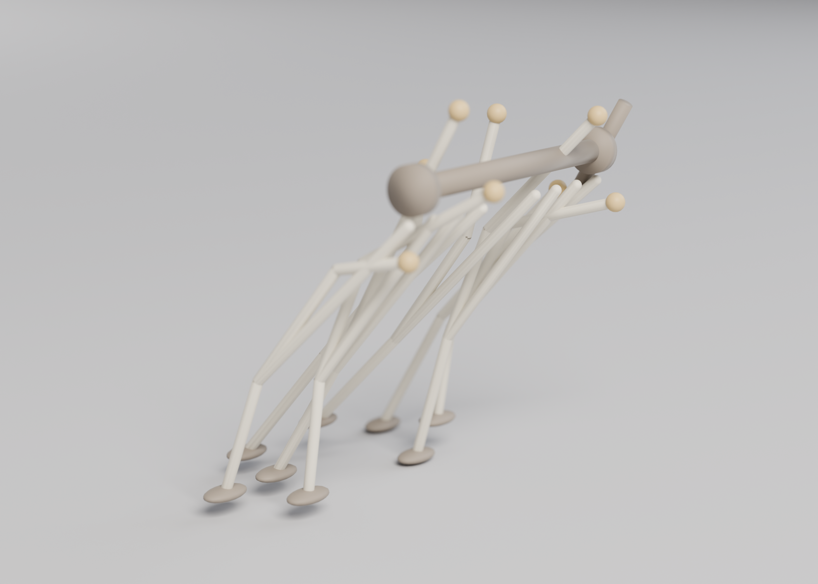
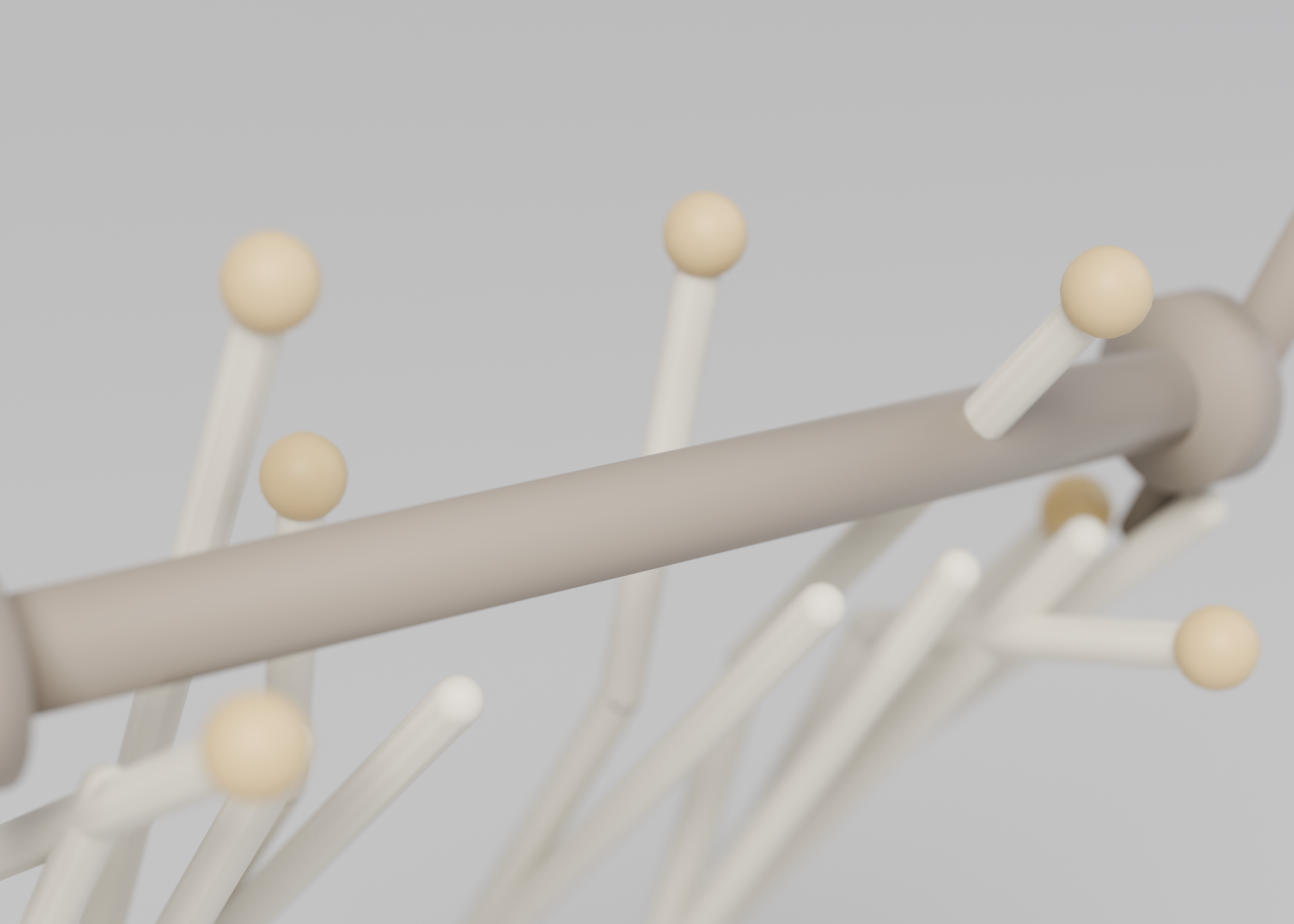
What can I customize?
Your choices go into the line you copy. Anything else is yours to edit, but it leaves the tested path.
What do I get?
-
spec.mdRequirements and acceptance checks.Wind walker
What this builds
A walking linkage, in the long tradition of wind-walking machines, modelled as code with its own documented constants (not a branded kit's parts). Link lengths, a foot path over a full crank revolution, and clearances are checked so the linkage does not intersect itself. Gait renders at several crank angles are written. Walking on sand, or in wind, is out of scope.
Read
spekkr.inputs.jsonfirst.scalemultiplies the link table.thicknessandclearancesize the bars and joints.legsandcrank_handlechange how complete the model is.toolis the modeller.Out of scope
- A branded walking-sculpture name in the id or the title.
- Walking on sand, or a wind test.
- A physical print or a kit of bought parts.
Requirements
Each requirement has an id. Checks name the id they cover.
R1. Lengths and foot path
- Link lengths are the constants in
design.mdtimesscale, within 0.05 mm * scale. - A kinematic model (or the mesh at stepped angles) traces the foot over one crank revolution. The path matches the polyline in
fixtures/walker-foot.jsonwithin 0.5 mm * scale. - At 36 steps of 10 degrees, no two bars illegally intersect, given
clearanceat the joints.
Accept when: lengths, the foot path, and the intersection check all match.
R2. Files and frames
- Export the parts or a posed assembly at 0, 90, 180, 270 degrees. Renders: a side view, a foot-path overlay, a top view, and a contact sheet of those angles.
- One command builds, traces, checks, and writes the renders. No sand, no wind, no print.
Accept when: the command passes for both tools, and a deliberately shortened link fails the path check.
R3. Inputs
- Numeric inputs are read from
spekkr.inputs.jsonand must stay inside the ranges in the Inputs table indesign.md. - A value outside a range is refused before modelling, with a message that names the key.
- Options add or remove the features in that table. The
toolswap selects CadQuery or OpenSCAD; both must meet the same numbers.
Accept when: default and one out-of-range value are handled as above, and a second legal input set still matches the formulas in
design.md.R4. Checks and report
- One command builds the model at the defaults and at the person's inputs, measures it against
design.md, and writes a short report. - A model broken on purpose, for example a wall thinner than
wall, must fail the report. - The command exports the files this spec asks for (STL, and STEP when the tool can). No physical print is required.
Accept when: the report says pass at the defaults and at the person's inputs, and fail on a deliberately broken model.
Verification
Linkage lengths match documented constants. The foot path and clearances over a full crank revolution are checked, including no illegal self-intersection. Gait renders at several angles are written. Walking on sand is out of scope. No physical print is required. The product name does not use a trademarked walking-sculpture name.
Definition of done
- Every acceptance check above runs from one command, and all pass at the person's inputs.
- A README says how to export, how the constants are listed, and that a walk on sand is not a check.
# Wind walker

## What this builds

A walking linkage, in the long tradition of wind-walking machines,
modelled as code with its own documented constants (not a branded kit's
parts). Link lengths, a foot path over a full crank revolution, and
clearances are checked so the linkage does not intersect itself. Gait
renders at several crank angles are written. Walking on sand, or in wind,
is out of scope.

Read `spekkr.inputs.json` first. `scale` multiplies the link table.
`thickness` and `clearance` size the bars and joints. `legs` and
`crank_handle` change how complete the model is. `tool` is the modeller.

## Out of scope

- A branded walking-sculpture name in the id or the title.
- Walking on sand, or a wind test.
- A physical print or a kit of bought parts.

## Requirements

Each requirement has an id. Checks name the id they cover.

### R1. Lengths and foot path

- Link lengths are the constants in `design.md` times `scale`, within 0.05
  mm * scale.
- A kinematic model (or the mesh at stepped angles) traces the foot over
  one crank revolution. The path matches the polyline in
  `fixtures/walker-foot.json` within 0.5 mm * scale.
- At 36 steps of 10 degrees, no two bars illegally intersect, given
  `clearance` at the joints.

Accept when: lengths, the foot path, and the intersection check all match.

### R2. Files and frames

- Export the parts or a posed assembly at 0, 90, 180, 270 degrees.
  Renders: a side view, a foot-path overlay, a top view, and a contact
  sheet of those angles.
- One command builds, traces, checks, and writes the renders. No sand, no
  wind, no print.

Accept when: the command passes for both tools, and a deliberately
shortened link fails the path check.

### R3. Inputs

- Numeric inputs are read from `spekkr.inputs.json` and must stay inside
  the ranges in the Inputs table in `design.md`.
- A value outside a range is refused before modelling, with a message that
  names the key.
- Options add or remove the features in that table. The `tool` swap
  selects CadQuery or OpenSCAD; both must meet the same numbers.

Accept when: default and one out-of-range value are handled as above, and
a second legal input set still matches the formulas in `design.md`.

### R4. Checks and report

- One command builds the model at the defaults and at the person's inputs,
  measures it against `design.md`, and writes a short report.
- A model broken on purpose, for example a wall thinner than `wall`, must
  fail the report.
- The command exports the files this spec asks for (STL, and STEP when the
  tool can). No physical print is required.

Accept when: the report says pass at the defaults and at the person's
inputs, and fail on a deliberately broken model.

## Verification

Linkage lengths match documented constants. The foot path and clearances
over a full crank revolution are checked, including no illegal
self-intersection. Gait renders at several angles are written. Walking on
sand is out of scope. No physical print is required. The product name does
not use a trademarked walking-sculpture name.

## Definition of done

- Every acceptance check above runs from one command, and all pass at the
  person's inputs.
- A README says how to export, how the constants are listed, and that a
  walk on sand is not a check.
-
design.mdLink constants, the foot-path fixture, and collision at crank steps.Design
This file fixes the geometry. How the model's code is organised is up to you, as long as the numbers here hold.
Constants
The link table (crank, rockers, shins, feet) is
fixtures/walker-links.json, in millimetres at scale 1. These are original constants for this spec, not a copy of a patented table presented as a product name.Path
The expected foot path is a closed loop, flatter at the bottom (the stance), in the fixture file. Tolerance 0.5 mm at scale 1.
Inputs
Key Label Default Notes scaleScale 1.0 A multiplier on the documented link lengths, from 0.5 to 2. thicknessBar thickness, mm 4.0 From 2 to 8. clearanceJoint clearance, mm 0.3 From 0.2 to 0.5. legsEight legs on If off, a single four-bar demo is built, still enough for the path check. crank_handleA crank handle on A handle to turn the crank in a desktop model. toolModelling tool cadquery CadQuery writes STEP and STL. OpenSCAD writes STL. Acceptance at the defaults
Millimetres. Default span 240, leg length 120, eight legs on, crank handle on. This is an original linkage, not a copy of a named walking machine.
Quantity Value Tolerance Source Overall span, feet planted 240.00 0.40 Left-most to right-most foot Leg length, hip to foot 120.00 0.20 Along the longest bar Crank radius 16.00 0.10 Of the driving crank Foot path, horizontal travel 36.00 0.40 One stride of a foot in the air Foot path, ground contact flatness 1.00 0.20 Z wander while planted A full crank turn is simulated in code. Each foot's path is written to a CSV and compared to the documented stride. If
legsis off, a single four-bar still has to match the path check. No physical cranking is required.Screenshots
These pictures are headless OpenSCAD renders of the reference model in
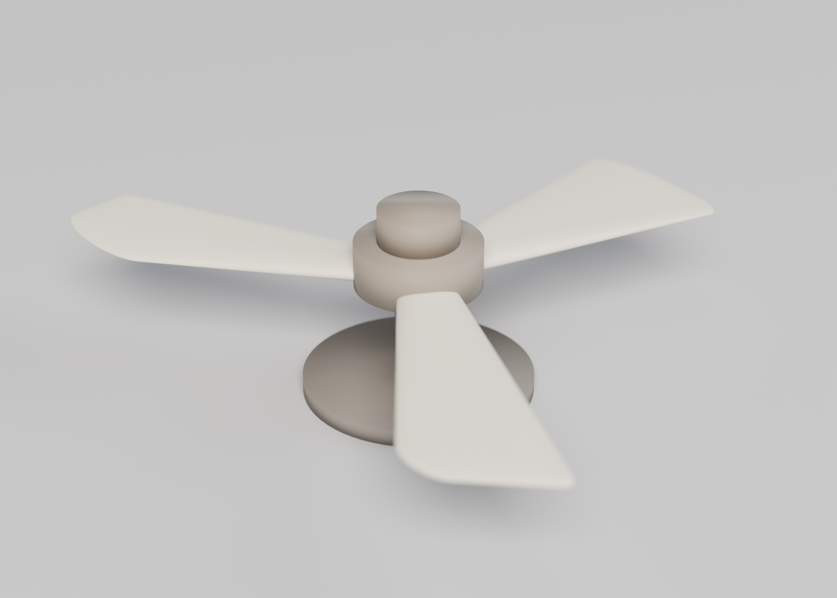
reference/model.scad, at the default inputs. They are not drawings of a product that has not been modelled. The first picture is the one Spekkr shows on the spec's card. A build may ship its own goldens; those goldens are of that build and do not have to match these frames pixel-for-pixel.File What it shows shots/walk.pngWalker 240 mm span, eight legs How to verify
- Build the model at the default inputs and at two other legal input sets.
- Measure every row of the acceptance table in this file; each must fall inside its tolerance. Use the solid itself or a mesh library on the exported STL, as
design.mdsays for the chosen tool. - Refuse at least one out-of-range input by name before modelling.
- Confirm each exported part is a manifold, watertight mesh, and that walls and print orientation hold where this file asks.
- Linkage lengths match documented constants. The foot path and clearances over a full crank revolution are checked, including no illegal self-intersection. Gait renders at several angles are written. Walking on sand is out of scope. No physical print is required. The product name does not use a trademarked walking-sculpture name.
# Design

This file fixes the geometry. How the model's code is organised is up to
you, as long as the numbers here hold.

## Constants

The link table (crank, rockers, shins, feet) is
`fixtures/walker-links.json`, in millimetres at scale 1. These are
original constants for this spec, not a copy of a patented table presented
as a product name.

## Path

The expected foot path is a closed loop, flatter at the bottom (the
stance), in the fixture file. Tolerance 0.5 mm at scale 1.

## Inputs

| Key | Label | Default | Notes |
| --- | --- | --- | --- |
| `scale` | Scale | 1.0 | A multiplier on the documented link lengths, from 0.5 to 2. |
| `thickness` | Bar thickness, mm | 4.0 | From 2 to 8. |
| `clearance` | Joint clearance, mm | 0.3 | From 0.2 to 0.5. |
| `legs` | Eight legs | on | If off, a single four-bar demo is built, still enough for the path check. |
| `crank_handle` | A crank handle | on | A handle to turn the crank in a desktop model. |
| `tool` | Modelling tool | cadquery | CadQuery writes STEP and STL. OpenSCAD writes STL. |

## Acceptance at the defaults

Millimetres. Default span 240, leg length 120, eight legs on, crank handle
on. This is an original linkage, not a copy of a named walking machine.

| Quantity | Value | Tolerance | Source |
| --- | --- | --- | --- |
| Overall span, feet planted | 240.00 | 0.40 | Left-most to right-most foot |
| Leg length, hip to foot | 120.00 | 0.20 | Along the longest bar |
| Crank radius | 16.00 | 0.10 | Of the driving crank |
| Foot path, horizontal travel | 36.00 | 0.40 | One stride of a foot in the air |
| Foot path, ground contact flatness | 1.00 | 0.20 | Z wander while planted |

A full crank turn is simulated in code. Each foot's path is written to a
CSV and compared to the documented stride. If `legs` is off, a single
four-bar still has to match the path check. No physical cranking is
required.

## Screenshots

These pictures are headless OpenSCAD renders of the reference model in
`reference/model.scad`, at the default inputs. They are not drawings of a
product that has not been modelled. The first picture is the one Spekkr
shows on the spec's card. A build may ship its own goldens; those goldens
are of that build and do not have to match these frames pixel-for-pixel.

| File | What it shows |
| --- | --- |
| `shots/walk.png` | Walker  240 mm span, eight legs |


## How to verify

1. Build the model at the default inputs and at two other legal input
sets.

2. Measure every row of the acceptance table in this file; each must fall
inside its tolerance. Use the solid itself or a mesh library on the
exported STL, as `design.md` says for the chosen tool.

3. Refuse at least one out-of-range input by name before modelling.

4. Confirm each exported part is a manifold, watertight mesh, and that
walls and print orientation hold where this file asks.

5. Linkage lengths match documented constants. The foot path and
clearances over a full crank revolution are checked, including no illegal
self-intersection. Gait renders at several angles are written. Walking on
sand is out of scope. No physical print is required. The product name does
not use a trademarked walking-sculpture name.
-
tasks.mdBuild tasks in order, each with a check.Tasks
Work in order. Finish a task's check before starting the next.
- Set up. Install the tool in the
toolinput (CadQuery or OpenSCAD) and a mesh library for the checks. Readspekkr.inputs.jsoninto one place at the top of the model. Check: an empty or trivial model is written and read back, and the inputs are visible in that source. - Lengths and foot path (R1). Build what
R1. Lengths and foot pathasks for, to the numbers indesign.md. In particular: Link lengths are the constants indesign.mdtimesscale, within 0.05 mm * scale. Check: theR1. Lengths and foot pathacceptance checks pass. - Files and frames (R2). Build what
R2. Files and framesasks for, to the numbers indesign.md. In particular: Export the parts or a posed assembly at 0, 90, 180, 270 degrees. Renders: a side view, a foot-path overlay, a top view, and a contact sheet of those angles. Check: theR2. Files and framesacceptance checks pass. - Inputs (R3). Build what
R3. Inputsasks for, to the numbers indesign.md. In particular: Numeric inputs are read fromspekkr.inputs.jsonand must stay inside the ranges in the Inputs table indesign.md. Check: theR3. Inputsacceptance checks pass. - Checks and report (R4). Build what
R4. Checks and reportasks for, to the numbers indesign.md. In particular: One command builds the model at the defaults and at the person's inputs, measures it againstdesign.md, and writes a short report. Check: theR4. Checks and reportacceptance checks pass. - Goldens and the report. Render the documented views of the default model. Run the one-command report at the defaults, at the person's inputs, and at one more legal set. Check: the report says pass throughout, and the rendered views are written next to the model.
- Finish. Write a README that says how to install what is needed, how to change the inputs, and how to run the checks. Run the one command from a clean folder. Check: every item under Definition of done in
spec.mdis true.
# Tasks

Work in order. Finish a task's check before starting the next.

1. **Set up.** Install the tool in the `tool` input (CadQuery or OpenSCAD)
and a mesh library for the checks. Read `spekkr.inputs.json` into one
place at the top of the model.
   Check: an empty or trivial model is written and read back, and the
inputs are visible in that source.

2. **Lengths and foot path (R1).** Build what `R1. Lengths and foot path`
asks for, to the numbers in `design.md`. In particular: Link lengths are
the constants in `design.md` times `scale`, within 0.05 mm * scale.
   Check: the `R1. Lengths and foot path` acceptance checks pass.

3. **Files and frames (R2).** Build what `R2. Files and frames` asks for,
to the numbers in `design.md`. In particular: Export the parts or a posed
assembly at 0, 90, 180, 270 degrees. Renders: a side view, a foot-path
overlay, a top view, and a contact sheet of those angles.
   Check: the `R2. Files and frames` acceptance checks pass.

4. **Inputs (R3).** Build what `R3. Inputs` asks for, to the numbers in
`design.md`. In particular: Numeric inputs are read from
`spekkr.inputs.json` and must stay inside the ranges in the Inputs table
in `design.md`.
   Check: the `R3. Inputs` acceptance checks pass.

5. **Checks and report (R4).** Build what `R4. Checks and report` asks
for, to the numbers in `design.md`. In particular: One command builds the
model at the defaults and at the person's inputs, measures it against
`design.md`, and writes a short report.
   Check: the `R4. Checks and report` acceptance checks pass.

6. **Goldens and the report.** Render the documented views of the default
model. Run the one-command report at the defaults, at the person's inputs,
and at one more legal set.
   Check: the report says pass throughout, and the rendered views are
written next to the model.

7. **Finish.** Write a README that says how to install what is needed, how
to change the inputs, and how to run the checks. Run the one command from
a clean folder.
   Check: every item under Definition of done in `spec.md` is true.
- Set up. Install the tool in the
-
reference/model.scadA parametric OpenSCAD reference of the default model, used to make the listing pictures. A build may use CadQuery or OpenSCAD and does not have to start from this file. -
shots/hero.pngStudio hero of the default model. -
shots/detail.pngCloser studio still of a joint, pocket, or surface.
Is it for me?
- Kind
- CAD
- Tools
- CadQuery, OpenSCAD
What does it need?
- Agent permissions
- shell
- Commands it runs
install CadQuery or OpenSCAD, whichever the tool input namesinstall a mesh library, such as trimesh
What changed?
- 0.2.015 Nov 2026Studio product shots from a shared Cycles rig (cyclorama, PLA materials), including a short loop when present.
- 0.1.014 Nov 2026First version.
For agents: start.md says how to build this spec, spec.json holds everything on this page, and bundle.tar.gz holds its files.