USB-C power input
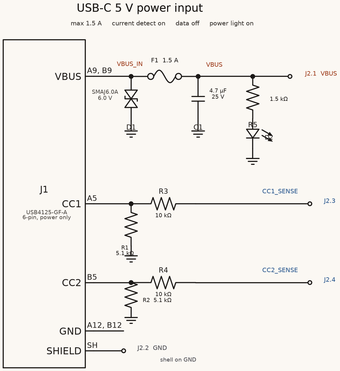
A 5 V power input from a USB-C socket, drawn as a circuit, with the resistors chargers look for and checks that catch the usual mistakes.
This is an electronics spec on Spekkr, published by onyx. It is listed with the other specs. Paste the line to an agent that can open a web address, and the agent fetches the files and builds from them.
- Spec
onyx/usb-c-power-input- Version
- 0.1.1
- Published by
- onyx
- Updated
- 14 Nov 2026
Build this spec
Build the spec at https://spekkr.com/onyx/usb-c-power-input/start.md.
Paste this to your AI agent. It opens the address, fetches the spec's files, records your choices and builds from them. Nothing to install, no account.
Published by onyx.
What does the result look like?
What can I customize?
Your choices go into the line you copy. Anything else is yours to edit, but it leaves the tested path.
What do I get?
-
spec.mdRequirements and acceptance checks.USB-C power input
What this builds
The part of a circuit board that takes 5 V from a USB-C socket: the socket, the two resistors a charger looks for before it supplies power, protection, and a way to learn how much current is on offer. It comes as a circuit with a parts list, and a script that checks the circuit against this spec.
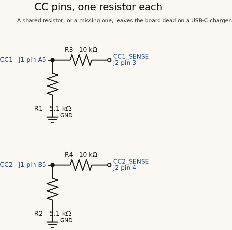
The classic mistake is to leave out the resistors on the CC pins, or to share one between both. Such a board works from an old USB-A charger and stays dead on a USB-C one. R2 and its check exist for that.
Read
spekkr.inputs.jsonfirst. The board draws at mostmax_currentamps.detect_current,data_linesandpower_ledadd parts.toolsays how the circuit is written.Out of scope
- USB Power Delivery and anything above 5 V.
- Supplying power to another device.
- The board's layout.
design.mdlists what the layout must respect. - Certification. This is a design to review before it is made. The checks catch the known mistakes, not every mistake.
Requirements
Each requirement has an id. Checks name the id they cover.
R1. The socket
- A USB Type-C receptacle. With
data_linesoff, a 6-pin power-only part is enough. With it on, a 16-pin USB 2.0 part. - Every VBUS pin is on one net,
VBUS_IN. Every GND pin and the shell are onGND. CC1andCC2are two separate nets.
Accept when: the netlist has
VBUS_IN,GND,CC1andCC2, every VBUS and GND pin of the socket is on its net, andCC1andCC2are different nets.R2. Ask for power
CC1has its own resistor of 5.1 kilohms, 1%, toGND. So hasCC2. They are two parts.- Nothing else connects
CC1orCC2toGND, to each other or toVBUS_IN.
Accept when: the check finds exactly one 5.1 kilohm resistor from each CC net to
GND, two different references, both marked 1% in the parts list.R3. Protect
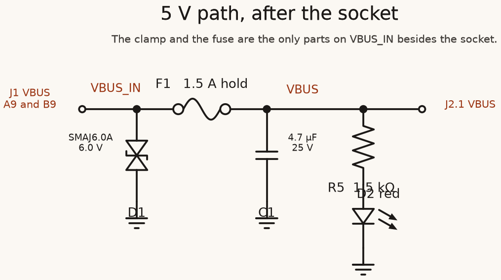
- A fuse that resets itself sits between
VBUS_INandVBUS, with a hold current of at leastmax_current. - A diode that clamps surges sits from
VBUS_INtoGND, with a working voltage of at least 5.5 V. - Everything downstream takes its power from
VBUS, never fromVBUS_IN.
Accept when: the only parts on
VBUS_INare the socket, the fuse and the clamp, and the parts list gives the fuse's hold current and the clamp's working voltage.R4. Do not ask for too much at once
- The capacitors on
VBUStogether are at least 1 microfarad and at most 10. A charger sees them the moment the cable goes in. - Each is rated for 16 V or more.
Accept when: the check adds up every capacitor on
VBUSand finds a total from 1 to 10 microfarads.R5. How much is on offer
Only if
detect_currentis on.CC1_SENSEandCC2_SENSEeach reach their CC net through a resistor of at least 10 kilohms, so that a fault on the cable cannot push a harmful current into whatever reads them.- A small function, in whatever language the person's firmware uses, turns the two voltages into what the source offers, by the table in
design.md.
Accept when: every row of the table of cases in
design.mdgives the answer listed.R6. Data
Only if
data_linesis on.- The socket's two D+ pins are joined on
USB_DPand its two D- pins onUSB_DN, so the plug works either way up. - A part made to protect USB data lines sits on both, next to the socket.
With
data_linesoff, the socket has no data pins, or they are marked as not connected.Accept when: the check finds both pins of each pair on its net, or with the option off finds no net on any data pin.
R7. Power light
Only if
power_ledis on.- An LED and a resistor in series from
VBUStoGND. The resistor is 1.5 kilohms, for about 2 mA through a red LED.
Accept when: the check finds the pair, and the resistor's value.
R8. What comes out
- A header carries
VBUSandGND, andCC1_SENSE,CC2_SENSE,USB_DPandUSB_DNwhen they exist. - A parts list as CSV: reference, value, tolerance or rating, footprint, and what the part is for.
- A netlist in KiCad's format, written by one command from the source.
Accept when: the command writes the netlist and the parts list, and every part in one is in the other.
R9. The check
- One script reads the netlist and the parts list and checks R1 to R8.
- It fails, with a message that names the requirement, when a CC resistor is removed, when both CC pins share one resistor, and when a 22 microfarad capacitor is put on
VBUS. - The tool's own electrical rules check reports no errors.
Accept when: the script passes on the circuit as built and fails on each of the three broken copies.
Definition of done
- Every acceptance check above runs from one command, and all pass at the person's inputs.
- A README says how to make the netlist, how to run the check, and lists what a person must still review before ordering boards: the layout rules in
design.mdand the choice of each part.
# USB-C power input

## What this builds

The part of a circuit board that takes 5 V from a USB-C socket: the socket, the
two resistors a charger looks for before it supplies power, protection, and a
way to learn how much current is on offer. It comes as a circuit with a parts
list, and a script that checks the circuit against this spec.

The classic mistake is to leave out the resistors on the CC pins, or to share
one between both. Such a board works from an old USB-A charger and stays dead on
a USB-C one. R2 and its check exist for that.

Read `spekkr.inputs.json` first. The board draws at most `max_current` amps.
`detect_current`, `data_lines` and `power_led` add parts. `tool` says how the
circuit is written.

## Out of scope

- USB Power Delivery and anything above 5 V.
- Supplying power to another device.
- The board's layout. `design.md` lists what the layout must respect.
- Certification. This is a design to review before it is made. The checks catch
  the known mistakes, not every mistake.

## Requirements

Each requirement has an id. Checks name the id they cover.

### R1. The socket

- A USB Type-C receptacle. With `data_lines` off, a 6-pin power-only part is
  enough. With it on, a 16-pin USB 2.0 part.
- Every VBUS pin is on one net, `VBUS_IN`. Every GND pin and the shell are on
  `GND`.
- `CC1` and `CC2` are two separate nets.

Accept when: the netlist has `VBUS_IN`, `GND`, `CC1` and `CC2`, every VBUS and GND
pin of the socket is on its net, and `CC1` and `CC2` are different nets.

### R2. Ask for power

- `CC1` has its own resistor of 5.1 kilohms, 1%, to `GND`. So has `CC2`. They are
  two parts.
- Nothing else connects `CC1` or `CC2` to `GND`, to each other or to `VBUS_IN`.

Accept when: the check finds exactly one 5.1 kilohm resistor from each CC net to
`GND`, two different references, both marked 1% in the parts list.

### R3. Protect

- A fuse that resets itself sits between `VBUS_IN` and `VBUS`, with a hold
  current of at least `max_current`.
- A diode that clamps surges sits from `VBUS_IN` to `GND`, with a working voltage
  of at least 5.5 V.
- Everything downstream takes its power from `VBUS`, never from `VBUS_IN`.

Accept when: the only parts on `VBUS_IN` are the socket, the fuse and the clamp,
and the parts list gives the fuse's hold current and the clamp's working voltage.

### R4. Do not ask for too much at once

- The capacitors on `VBUS` together are at least 1 microfarad and at most 10. A
  charger sees them the moment the cable goes in.
- Each is rated for 16 V or more.

Accept when: the check adds up every capacitor on `VBUS` and finds a total from 1
to 10 microfarads.

### R5. How much is on offer

Only if `detect_current` is on.

- `CC1_SENSE` and `CC2_SENSE` each reach their CC net through a resistor of at
  least 10 kilohms, so that a fault on the cable cannot push a harmful current
  into whatever reads them.
- A small function, in whatever language the person's firmware uses, turns the two
  voltages into what the source offers, by the table in `design.md`.

Accept when: every row of the table of cases in `design.md` gives the answer
listed.

### R6. Data

Only if `data_lines` is on.

- The socket's two D+ pins are joined on `USB_DP` and its two D- pins on `USB_DN`,
  so the plug works either way up.
- A part made to protect USB data lines sits on both, next to the socket.

With `data_lines` off, the socket has no data pins, or they are marked as not
connected.

Accept when: the check finds both pins of each pair on its net, or with the
option off finds no net on any data pin.

### R7. Power light

Only if `power_led` is on.

- An LED and a resistor in series from `VBUS` to `GND`. The resistor is 1.5
  kilohms, for about 2 mA through a red LED.

Accept when: the check finds the pair, and the resistor's value.

### R8. What comes out

- A header carries `VBUS` and `GND`, and `CC1_SENSE`, `CC2_SENSE`, `USB_DP` and
  `USB_DN` when they exist.
- A parts list as CSV: reference, value, tolerance or rating, footprint, and what
  the part is for.
- A netlist in KiCad's format, written by one command from the source.

Accept when: the command writes the netlist and the parts list, and every part in
one is in the other.

### R9. The check

- One script reads the netlist and the parts list and checks R1 to R8.
- It fails, with a message that names the requirement, when a CC resistor is
  removed, when both CC pins share one resistor, and when a 22 microfarad
  capacitor is put on `VBUS`.
- The tool's own electrical rules check reports no errors.

Accept when: the script passes on the circuit as built and fails on each of the
three broken copies.

## Definition of done

- Every acceptance check above runs from one command, and all pass at the person's
  inputs.
- A README says how to make the netlist, how to run the check, and lists what a
  person must still review before ordering boards: the layout rules in
  `design.md` and the choice of each part.
-
design.mdNets, values, thresholds and what the checks read.Design
This file fixes the nets, the values and the thresholds. Which exact parts and footprints to use is up to you; write them in the parts list.
Nets
Net Is VBUS_IN5 V straight from the socket VBUS5 V after the fuse; what the rest of the board uses GNDGround, and the socket's shell CC1,CC2The socket's two configuration pins CC1_SENSE,CC2_SENSEThe same, behind a resistor (only if detect_currentis on)USB_DP,USB_DNUSB 2.0 data (only if data_linesis on)Parts and values
Part Value Why Resistor, CC1toGND5.1 kilohms, 1% Tells a USB-C source that a device is attached and wants 5 V Resistor, CC2toGND5.1 kilohms, 1% The same, for a plug the other way up Resettable fuse Hold current at least the max_currentinputOpens on a short downstream Surge clamp, VBUS_INtoGNDWorking voltage at least 5.5 V Takes the spike when a cable is pulled Capacitors on VBUS1 to 10 microfarads in total, 16 V or more Steadies the supply without a large inrush Sense resistors 10 kilohms or more Limits current into the reader if CC touches a higher voltage LED resistor 1.5 kilohms (5 V - 2 V) / 2 mA A source that offers more than 5 V over Power Delivery can put up to 20 V on a pin next to CC inside the plug. Anything on a CC net must survive that touching it. A plain resistor does.
How much the source offers
A source says how much current it will give by how hard it pulls the CC line up. Only the CC pin the cable connects carries a voltage; the other reads near zero. Read both and take the higher.
Higher of the two voltages Means A device may draw Under 0.2 V Nothing attached Nothing 0.2 V to under 0.66 V Default USB power 0.5 A 0.66 V to under 1.23 V 1.5 A offered 1.5 A 1.23 V and over 3 A offered 3 A These thresholds are from the USB Type-C specification's table of voltages on a sink's CC pins. Confirm them in the current release before relying on them.
Cases for R5, as millivolts on
CC1_SENSEandCC2_SENSE:CC1 CC2 Answer 0 0 nothing attached 420 0 0.5 A 0 420 0.5 A 659 0 0.5 A 660 0 1.5 A 0 940 1.5 A 1229 0 1.5 A 1230 0 3 A 0 1680 3 A 199 0 nothing attached If the board may draw more than the source offers, it must hold back. That is the firmware's job, and the README says so.
What the check reads
The netlist names each part's reference and value and lists each net's pins. The check works from those and from the parts list, not from a drawing:
- A resistor "from A to B" is a two-pin part with one pin on each net.
- Values are compared as numbers:
5.1k,5k1and5100are the same. - With
toolset toskidl, run its own rules check as well. Withkicad, runkicad-cli sch ercand export the netlist withkicad-cli sch export netlist.
For whoever lays out the board
- The two CC resistors and the clamp sit within a few millimetres of the socket.
- The trace from
VBUS_INthrough the fuse toVBUSis wide enough for themax_currentinput: at least 0.6 mm for 1.5 A and 1.5 mm for 3 A, on an outer layer of ordinary 1 oz copper. USB_DPandUSB_DNrun side by side, the same length, as a pair with 90 ohms between them.
Named here
- When the person names no firmware language, the function in R5 is written in Python.
What this spec leaves to you
Where this spec names something, use that name, so that two builds of it agree. Where it does not, the choice is yours. List what you chose in the README.
# Design

This file fixes the nets, the values and the thresholds. Which exact parts and
footprints to use is up to you; write them in the parts list.

## Nets

| Net | Is |
| --- | --- |
| `VBUS_IN` | 5 V straight from the socket |
| `VBUS` | 5 V after the fuse; what the rest of the board uses |
| `GND` | Ground, and the socket's shell |
| `CC1`, `CC2` | The socket's two configuration pins |
| `CC1_SENSE`, `CC2_SENSE` | The same, behind a resistor (only if `detect_current` is on) |
| `USB_DP`, `USB_DN` | USB 2.0 data (only if `data_lines` is on) |

## Parts and values

| Part | Value | Why |
| --- | --- | --- |
| Resistor, `CC1` to `GND` | 5.1 kilohms, 1% | Tells a USB-C source that a device is attached and wants 5 V |
| Resistor, `CC2` to `GND` | 5.1 kilohms, 1% | The same, for a plug the other way up |
| Resettable fuse | Hold current at least the `max_current` input | Opens on a short downstream |
| Surge clamp, `VBUS_IN` to `GND` | Working voltage at least 5.5 V | Takes the spike when a cable is pulled |
| Capacitors on `VBUS` | 1 to 10 microfarads in total, 16 V or more | Steadies the supply without a large inrush |
| Sense resistors | 10 kilohms or more | Limits current into the reader if CC touches a higher voltage |
| LED resistor | 1.5 kilohms | (5 V - 2 V) / 2 mA |

A source that offers more than 5 V over Power Delivery can put up to 20 V on a
pin next to CC inside the plug. Anything on a CC net must survive that touching
it. A plain resistor does.

## How much the source offers

A source says how much current it will give by how hard it pulls the CC line up.
Only the CC pin the cable connects carries a voltage; the other reads near zero.
Read both and take the higher.

| Higher of the two voltages | Means | A device may draw |
| --- | --- | --- |
| Under 0.2 V | Nothing attached | Nothing |
| 0.2 V to under 0.66 V | Default USB power | 0.5 A |
| 0.66 V to under 1.23 V | 1.5 A offered | 1.5 A |
| 1.23 V and over | 3 A offered | 3 A |

These thresholds are from the USB Type-C specification's table of voltages on a
sink's CC pins. Confirm them in the current release before relying on them.

Cases for R5, as millivolts on `CC1_SENSE` and `CC2_SENSE`:

| CC1 | CC2 | Answer |
| --- | --- | --- |
| 0 | 0 | nothing attached |
| 420 | 0 | 0.5 A |
| 0 | 420 | 0.5 A |
| 659 | 0 | 0.5 A |
| 660 | 0 | 1.5 A |
| 0 | 940 | 1.5 A |
| 1229 | 0 | 1.5 A |
| 1230 | 0 | 3 A |
| 0 | 1680 | 3 A |
| 199 | 0 | nothing attached |

If the board may draw more than the source offers, it must hold back. That is the
firmware's job, and the README says so.

## What the check reads

The netlist names each part's reference and value and lists each net's pins. The
check works from those and from the parts list, not from a drawing:

- A resistor "from A to B" is a two-pin part with one pin on each net.
- Values are compared as numbers: `5.1k`, `5k1` and `5100` are the same.
- With `tool` set to `skidl`, run its own rules check as well. With `kicad`, run
  `kicad-cli sch erc` and export the netlist with `kicad-cli sch export netlist`.

## For whoever lays out the board

- The two CC resistors and the clamp sit within a few millimetres of the socket.
- The trace from `VBUS_IN` through the fuse to `VBUS` is wide enough for the
  `max_current` input: at least 0.6 mm for 1.5 A and 1.5 mm for 3 A, on an
  outer layer of ordinary 1 oz copper.
- `USB_DP` and `USB_DN` run side by side, the same length, as a pair with 90 ohms
  between them.

## Named here

- When the person names no firmware language, the function in R5 is written in
  Python.

## What this spec leaves to you

Where this spec names something, use that name, so that two builds of it agree.
Where it does not, the choice is yours. List what you chose in the README.
-
tasks.mdBuild tasks in order, each with a check.Tasks
Work in order. Finish a task's check before starting the next.
- Set up. Install the tool in the
toolinput. Decide on each part and its footprint, and write them down in the parts list. Check: an empty circuit writes an empty netlist. - Socket and CC resistors (R1, R2). With
data_linesdeciding which socket. Check: the R1 and R2 checks pass. - Protection and capacitors (R3, R4). Use the
max_currentinput. Check: the R3 and R4 checks pass. - Sense outputs (R5). Only if
detect_currentis on. The two resistors, and the function with its table of cases. Check: every case indesign.mdgives its answer. - Data (R6) and the light (R7). As
data_linesandpower_ledsay. Check: the R6 and R7 checks pass. - What comes out (R8). Check: the R8 check passes.
- The check itself (R9). Break the circuit the three ways R9 names and see each one caught. Check: the R9 checks pass.
- Finish. Write the README and run the command from a clean folder. Check: every item under "Definition of done" in
spec.mdis true.
# Tasks

Work in order. Finish a task's check before starting the next.

1. **Set up.** Install the tool in the `tool` input. Decide on each part and its
   footprint, and write them down in the parts list.
   Check: an empty circuit writes an empty netlist.

2. **Socket and CC resistors (R1, R2).** With `data_lines` deciding which socket.
   Check: the R1 and R2 checks pass.

3. **Protection and capacitors (R3, R4).** Use the `max_current` input.
   Check: the R3 and R4 checks pass.

4. **Sense outputs (R5).** Only if `detect_current` is on. The two resistors, and
   the function with its table of cases.
   Check: every case in `design.md` gives its answer.

5. **Data (R6) and the light (R7).** As `data_lines` and `power_led` say.
   Check: the R6 and R7 checks pass.

6. **What comes out (R8).**
   Check: the R8 check passes.

7. **The check itself (R9).** Break the circuit the three ways R9 names and see
   each one caught.
   Check: the R9 checks pass.

8. **Finish.** Write the README and run the command from a clean folder.
   Check: every item under "Definition of done" in `spec.md` is true.
- Set up. Install the tool in the
Is it for me?
- Kind
- electronics
- Tools
- KiCad, SKiDL
What does it need?
- Agent permissions
- shell
- Commands it runs
install SKiDL or KiCad, whichever the tool input names
What changed?
- 0.1.114 Nov 2026Says "person" where it said "buyer".
- 0.1.014 Nov 2026Moved from dwrtz/usb-c-power-input.
For agents: start.md says how to build this spec, spec.json holds everything on this page, and bundle.tar.gz holds its files.